Why Measure Resistance?
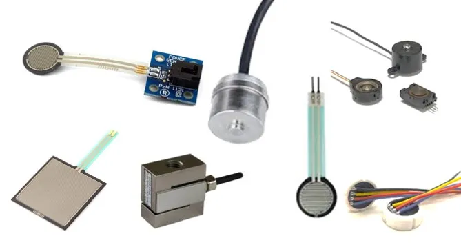
Key Applications
- Light-dependent resistors (LDR)
- Thermistors for temperature sensing
- Flex sensors
- Potentiometers
- Strain gauges
Measurement Principle
Voltage Divider Circuit
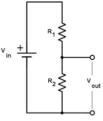
Vout = Vin × (R2 / (R1 + R2))
Arduino Implementation
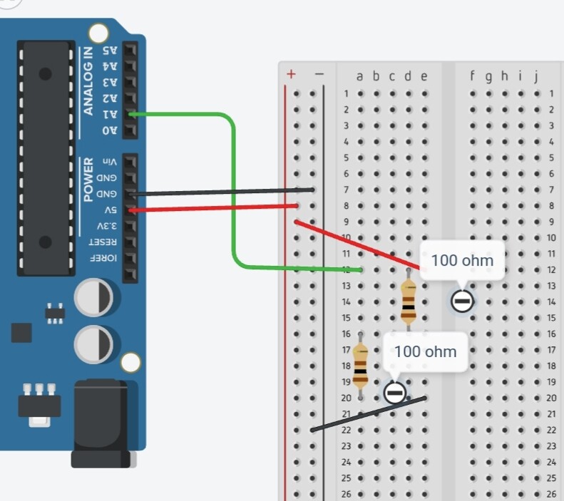
Analog input measures voltage between resistors
Implementation Code
const int sensorPin = A0;
const int Rc = 1500;  // Calibration resistor value

void setup() {
  Serial.begin(9600);
}

void loop() {
  int raw = analogRead(sensorPin);
  float voltage = raw * (5.0 / 1023.0);
  float Rsensor = Rc * (1023.0 / raw - 1);

  Serial.print("Resistance: ");
  Serial.println(Rsensor);
  delay(1000);
}
const int sensorPin = A0;
const long Rc = 1500L;  // Calibration resistor value

void setup() {
  Serial.begin(9600);
}

void loop() {
  int raw = analogRead(sensorPin);
  long Rsensor = (1024L * Rc) / raw - Rc;

  Serial.print("Resistance: ");
  Serial.println(Rsensor);
  delay(1000);
}
Choosing Calibration Resistor
Selection Guidelines
| Sensor Range | Recommended Rc |
|---|---|
| 100Ω - 1kΩ | 1kΩ |
| 1kΩ - 10kΩ | 4.7kΩ |
| 10kΩ - 100kΩ | 47kΩ |
Current Considerations
- Max current at 5V: 5mA
- Power dissipation: 0.125W max
- ADC input impedance: 10MΩ
Resistance Calculator
Calculated Resistance: