Introduction
In previous lessons, we learned how to use digital inputs in Arduino. In this lesson, we will learn how to use analog inputs, how they work, and their characteristics.
Analog inputs work similarly to digital inputs, but internally, there are significant differences. Therefore, to understand their use correctly, we need to look at some basic theories.
What are Analog Inputs?
Analog inputs work with analog signals. An analog signal is a signal that can take any value within a specific range, such as voltage between 0V and 5V.
In contrast, a digital signal can only take two values: HIGH or LOW (e.g., 0V or 5V).
In automation systems, analog inputs are usually fewer in number, slower, and more expensive than digital inputs. In the case of Arduino, the number of analog inputs varies by model:
- Arduino Uno and Mini Pro boards have 6 analog inputs.
- Arduino Mega boards have 16 analog inputs.
Measurement Resolution
To understand the resolution of analog inputs, we need to understand how the Analog-to-Digital Converter (ADC) works.
The ADC converts the analog measurement into a digital value encoded with N bits. In the case of Arduino Uno, Mini Pro, and Mega, the resolution is 10 bits, providing 1024 digital levels.
This means the measurement resolution is ±2.44mV when using a 5V reference voltage.
Reference Voltage (AREF)
Arduino allows changing the reference voltage used by the ADC. You can change the reference voltage using the analogReference() function.
Possible values are:
DEFAULT: The default value, which is 5V or 3.3V depending on the model.INTERNAL: 1.1V (for Atmega 168 and 328).EXTERNAL: An external voltage applied to the AREF pin.
If you change the reference voltage, you must set the mode using analogReference() before taking any analog readings.
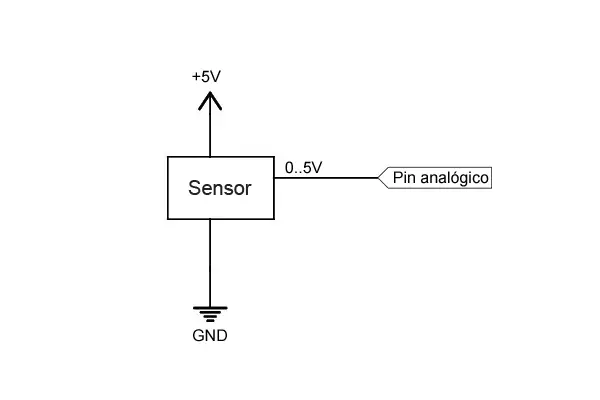
Connecting Analog Inputs
Suppose we have an analog sensor that provides a signal between 0V and 5V. It can be connected as follows:
Code in Arduino
The code for reading analog inputs is very simple. Here is an example of reading a value from an analog sensor:
const int sensorPin = A0;  // Connect the sensor to pin A0
int sensorValue;  // Variable to store the read value (0 to 1023)

void setup() {
Serial.begin(9600);  // Start serial communication
}

void loop() {
sensorValue = analogRead(sensorPin);  // Read the analog value

// Send the value to the serial monitor
Serial.println(sensorValue);
delay(1000);  // Small delay
}
If you want to convert the read value to voltage, you can use the following code:
const int sensorPin = A0;  // Connect the sensor to pin A0
int sensorValue;  // Variable to store the read value (0 to 1023)
float voltage;  // Variable to store the voltage (0.0 to 5.0)

void setup() {
Serial.begin(9600);  // Start serial communication
}

void loop() {
sensorValue = analogRead(sensorPin);  // Read the analog value
voltage = (sensorValue / 1023.0) * 5.0;  // Convert the value to voltage

// Send the voltage to the serial monitor
Serial.println(voltage);
delay(1000);  // Small delay
}
Reading Values Greater Than 5V
If you need to read a voltage higher than 5V, you can use a voltage divider to reduce the voltage to a safe range.
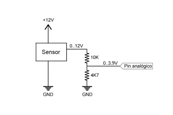
In this case, the analog pin will receive a voltage between 0 and 3.84V, which is within the safe range.