What is an Optocoupler?
An optocoupler uses light to connect two circuits while maintaining galvanic isolation. It protects control electronics from overvoltage, noise, and spikes.
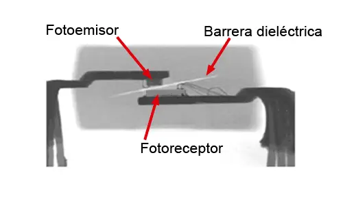
How Does an Optocoupler Work?
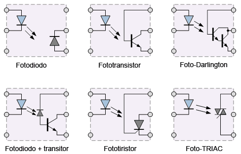
Optocouplers consist of an IR LED and a photoreceptor (transistor, photodiode, or phototriac) inside a single package. Light transmits the signal across circuits.
Using Optocouplers with Arduino
Optocouplers can isolate Arduino signals when emitting or receiving. Below are two common configurations.
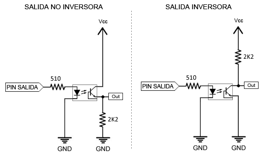
1. Arduino Emitting a Signal
Connect the primary circuit (LED side) to Arduino, adding a current-limiting resistor. The secondary side behaves like a switch for the load.
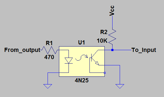
2. Arduino Receiving a Signal
Use the secondary side to trigger Arduino as if it were reading a button input.
Example Code
// Example: Reading an optocoupler signal with Arduino
const int optoPin = 2;

void setup() {
    pinMode(optoPin, INPUT_PULLUP);
    Serial.begin(9600);
}

void loop() {
    int state = digitalRead(optoPin);
    if (state == LOW) {
        Serial.println("Signal received!");
    }
    delay(100);
}
Conclusion
Optocouplers provide an effective way to isolate and protect your Arduino projects. Always choose the right model for your voltage, current, and speed requirements.