Introduction
In previous lessons, we learned how to use digital inputs to receive signals from the external world. However, if we can only read data, automation wouldn't be very useful (at least, it would be less useful than it is now).
In this lesson, we will learn how to use digital outputs in Arduino to interact with the external world.
What are Digital Outputs?
A digital signal can only change between two values, which we call -Vcc and +Vcc (for example, 0V and 5V).
Digital outputs are devices that allow changing the voltage to one of these two values through programming. Therefore, we can use them to interact with the surrounding environment.
In Arduino, the typical voltage values for -Vcc and +Vcc are 0V (GND) and 5V. However, some Arduino models operate at 3.3V, such as some Mini and Nano boards and ARM-based boards like the Arduino Due.
Number of Digital Outputs
All digital pins in Arduino can function as digital outputs (which is why they are called I/O, or Input/Output).
The number of digital outputs depends on the board model we are using:
- The Arduino Uno and Nano boards have 22 pins that can be used as digital outputs.
- The Arduino Mini board has 20 digital pins.
- The Arduino Mega board has up to 70 digital pins.
Maximum Current for Digital Outputs
Digital outputs in automation are not designed to provide high power but to interact with other electronics or automation systems.
The maximum current a pin can provide is 40 mA, but the recommended value is 20 mA. Additionally, there are other power-related limitations:
- The total current for all outputs must be less than 300 mA.
- It cannot exceed 150 mA per group of pins.
This power is sufficient to drive a small LED or a small servo motor, but it is not enough to drive larger loads like big motors or relays.
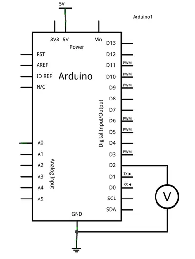
Connecting Digital Outputs
To test the operation of digital outputs, we can measure the voltage between the digital pin and GND using a multimeter.
Code in Arduino
The code to turn a digital pin on and off is very simple. Here is an example to turn an LED on and off:
const int pin = 2;  // Connect the LED to pin 2

void setup() {
  pinMode(pin, OUTPUT);  // Configure the pin as an output
}

void loop() {
  digitalWrite(pin, HIGH);  // Turn on the LED
  delay(1000);  // Wait for 1 second
  digitalWrite(pin, LOW);  // Turn off the LED
  delay(1000);  // Wait for 1 second
}
Here is another example to control the digital output through serial communication:
const int pin = 2;  // Connect the LED to pin 2
int option;

void setup() {
  Serial.begin(9600);  // Start serial communication
  pinMode(pin, OUTPUT);  // Configure the pin as an output
}

void loop() {
  if (Serial.available() > 0) {  // If data is available
    char option = Serial.read();  // Read the data
    if (option == '0') {  // If the value is 0
      digitalWrite(pin, LOW);  // Turn off the LED
    } else if (option == '1') {  // If the value is 1
      digitalWrite(pin, HIGH);  // Turn on the LED
    }
    delay(200);  // Small delay
  }
}