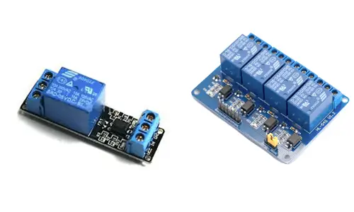
What is a Relay?
A relay is an electromechanical switch that allows Arduino to control high-voltage loads. It has two circuits:
- Primary Circuit: Controlled by Arduino's low voltage signal.
- Secondary Circuit: Responsible for controlling the high-voltage load.
How Does a Relay Work?
Relays use an internal coil to create a magnetic field, pivoting an armature to switch between its Normally Open (NO) and Normally Closed (NC) terminals. The load is connected to the Common (C) terminal and either NO or NC depending on desired behavior.

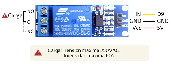
Assembly Diagram
Connecting a relay to Arduino is straightforward. Use commercial relay boards with Vcc, GND, and signal pins for Arduino, and connect the load to the Common (C), Normally Open (NO), or Normally Closed (NC) terminals.
Example Code
Below is an example code that alternates the relay state every 10 seconds:
// Example: Controlling a relay with Arduino
const int pin = 9;

void setup() {
    Serial.begin(9600);    // Start Serial communication
    pinMode(pin, OUTPUT);  // Set pin as OUTPUT
}

void loop() {
    digitalWrite(pin, HIGH);   // Turn relay ON
    delay(10000);              // Wait 10 seconds
    digitalWrite(pin, LOW);    // Turn relay OFF
    delay(10000);              // Wait 10 seconds
}
Conclusion
Relays are invaluable for controlling high-voltage devices with Arduino. Always ensure proper isolation and use components like optocouplers for added safety. Relays cannot handle PWM signals due to their switching time, so use other components like MOSFETs for such tasks.