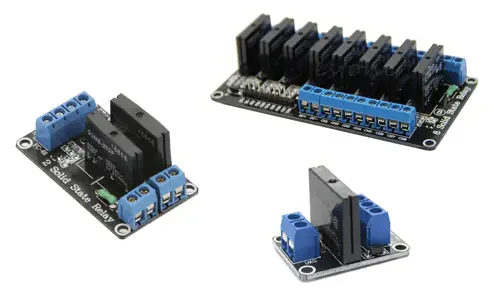
What is a Solid State Relay?
A Solid State Relay (SSR) is a semiconductor-based device that behaves like a traditional relay but lacks moving parts, making it faster, more durable, and silent. It is ideal for controlling high-voltage loads with Arduino.
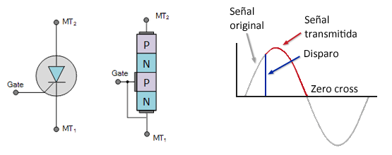
How Does a Solid State Relay Work?
An SSR uses a triac to control AC loads. The triac conducts electricity in both positive and negative AC cycles and deactivates at zero crossing. Optocouplers ensure isolation between the high-power and control circuits.
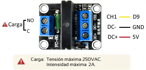
Connection Diagram
Connect the load to the SSR terminals and the control pins (DC+ and DC-) to Arduino's 5V and GND. The signal pin (CH1) is connected to a digital output on Arduino to switch the relay on or off.
Example Code
The following example toggles the SSR every 10 seconds, turning the connected load on and off.
// Example: Controlling an SSR with Arduino
const int pin = 9;

void setup()
{
    Serial.begin(9600);    // Start Serial communication
    pinMode(pin, OUTPUT);  // Set pin as OUTPUT
}

void loop()
{
    digitalWrite(pin, HIGH);   // Turn SSR ON
    delay(10000);              // Wait 10 seconds
    digitalWrite(pin, LOW);    // Turn SSR OFF
    delay(10000);              // Wait 10 seconds
}
Conclusion
Solid State Relays provide a reliable and silent way to control high-power AC loads with Arduino. They are faster and more durable than conventional relays but require proper heat dissipation for large loads. They cannot be used for PWM control of AC loads without additional components for synchronization.